Title: Design and Implementation of a Versatile 7-Segment Display Clock with Alarm Functionality
In the realm of timekeeping innovation, our project stands as an embodiment of precision and versatility. Our endeavor focuses on the development of a sophisticated 7-segment display system adept at serving both 12-hour and 24-hour clock formats while seamlessly exhibiting the current time. Central to this design is the integration of decade counter integrated circuits (ICs), meticulously orchestrated to track time with unparalleled accuracy and to govern the display mechanism. At its core, our project aspires to realize a clock operating at a harmonious frequency of 1Hz, ensuring a steadfast and reliable representation of time. However, our ambitions don't stop there; we've incorporated a distinctive feature that elevates its utility—a configurable alarm system. This alarm, triggered at precise 15-minute intervals, manifests as a blinking LED, offering a subtle yet effective notification. Crucially, we've empowered users with autonomy over their temporal experience. The interface provides intuitive controls for time adjustment, allowing individuals to personalize the clock to align seamlessly with their preferences. This user-friendly functionality ensures a tailored and user-centric timekeeping experience.
Project Objectives:
- Design a large 7-segment based display that shows the time using Logism Evolution
- Building PCB on easy EDA
- Timer designed to have a 15minutes alarm
- Timer built for 12hour clock and 24hour clock
View Components
Logism Flow
The operational methodology of this asynchronous timekeeping device integrates several key components to accurately display time. It relies on two separate decade counters to independently track minutes and seconds, with their 4-bit outputs driving BCD to 7 segment displays for visual representation. Managing hours is facilitated by a single hex counter cycling from 1 to 12, its 4-bit outputs transformed into a two-digit number using AND-OR logic gates, then showcased on dedicated 7-segment displays. Operating autonomously, each component functions asynchronously yet synergistically to deliver precise time tracking. Below shows designs of the 12hour and 24hour timer.
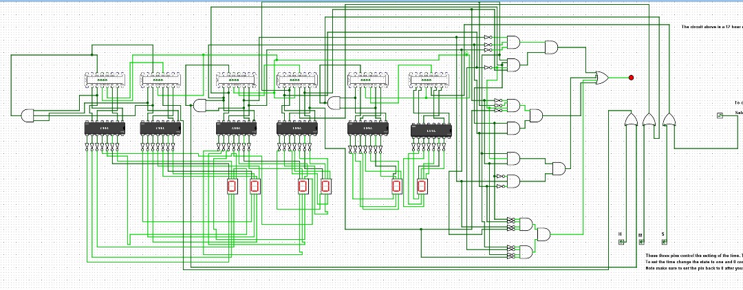
Fig 1a: Schematic of 12 hour timer on Logism
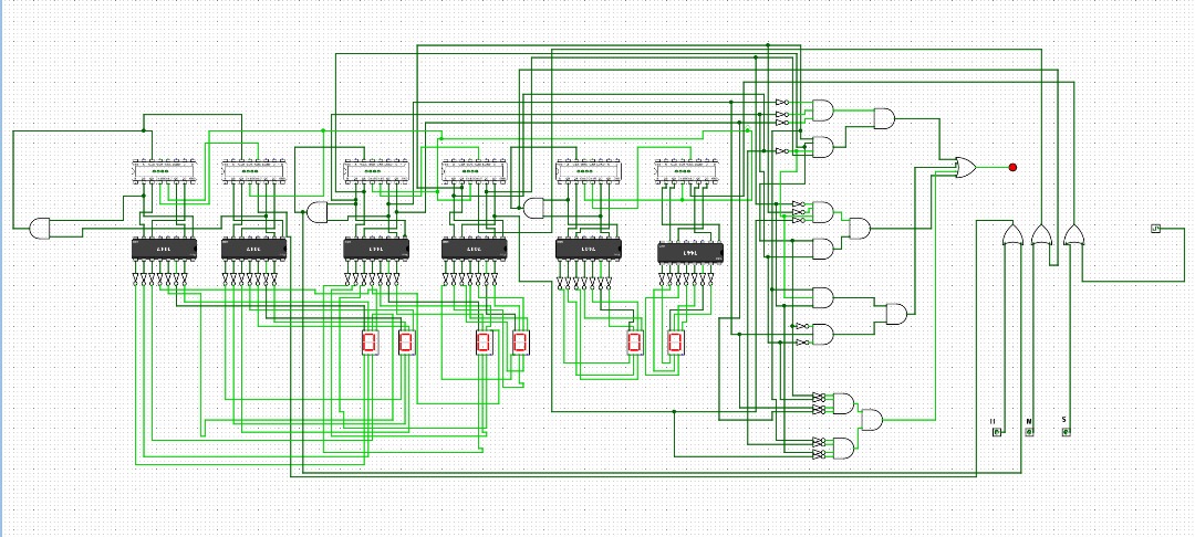
Fig 1b: Schematic of 24 hour timer on Logism
Manual Clock Setting
To manually set the timer, a specific procedure is followed using the clock signal, an OR gate, and an enable pin. The clock signal connects to an input of an OR gate, which, in conjunction with the enable pin, regulates the input into the decade counter's count-up mechanism. The output of this OR gate directly feeds into the count-up input of the decade counter. To initiate manual clocking adjustments, the enable pin is alternated between states of 1 and 0 in a repetitive manner until the user reaches their desired set point. This cyclical activation and deactivation of the enable pin control the manual advancement of the decade counter, allowing precise adjustments to the timer settings. NB: Reset the enable pin back to 0 after setting the time.
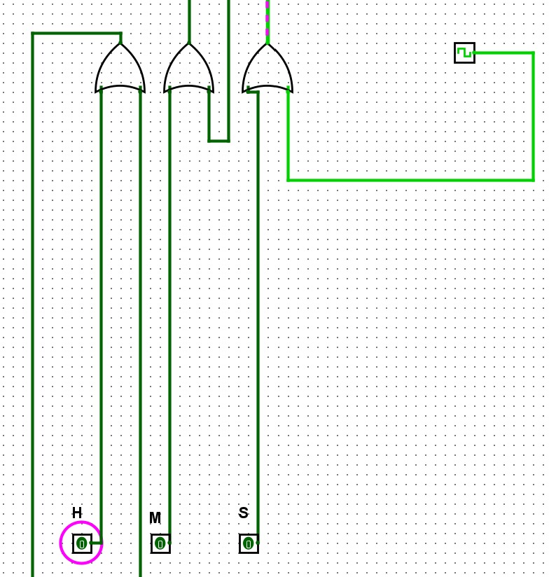
Fig 1c: Manual time setting logic
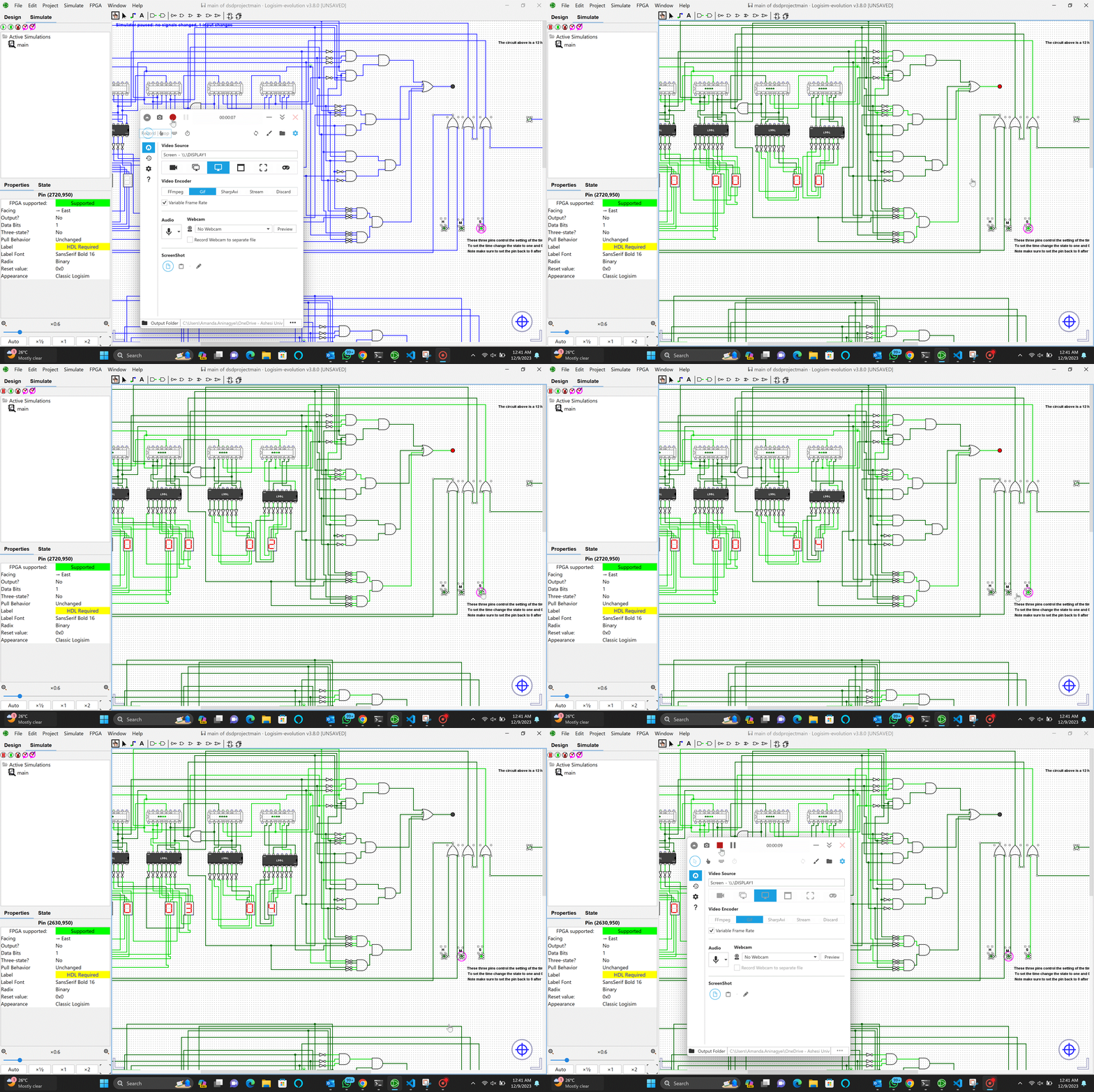
Fig 1d: Manual setting timer
15 minutes Alarm trigger
To activate the 15-minute alarm trigger, a specialized arrangement is established by linking the segments responsible for displaying 15, 30, 45, and 60 on the 7-segment display through a sequence of logic gates. These logic gates are strategically connected to an LED, serving as the signaling mechanism for the alarm. When the time counters reach 15, 30, 45, or 60 minutes, this configured logic gate sequence activates
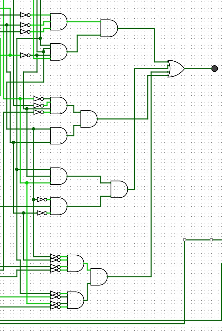
Fig 1e: Logic behind triggering alarm
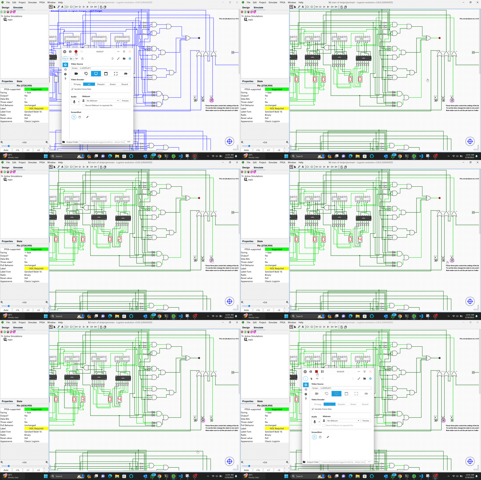
Fig 1f: Simulation of 15minutes alarm trigger
Easy EDA Schematic Design
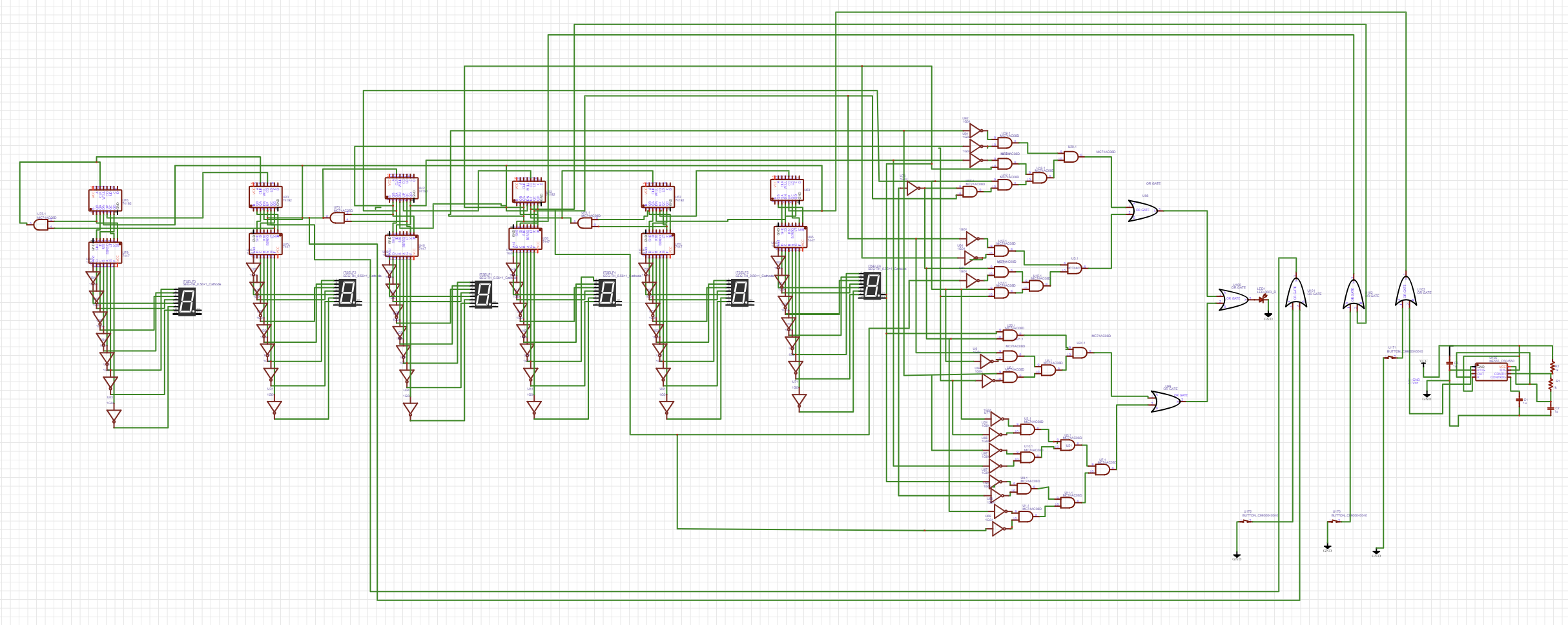
Fig 2a: Timer schematic on Easy EDA

Timer PCB
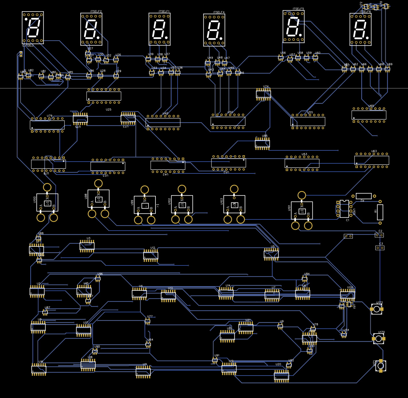
Timer PCB on Easy EDA
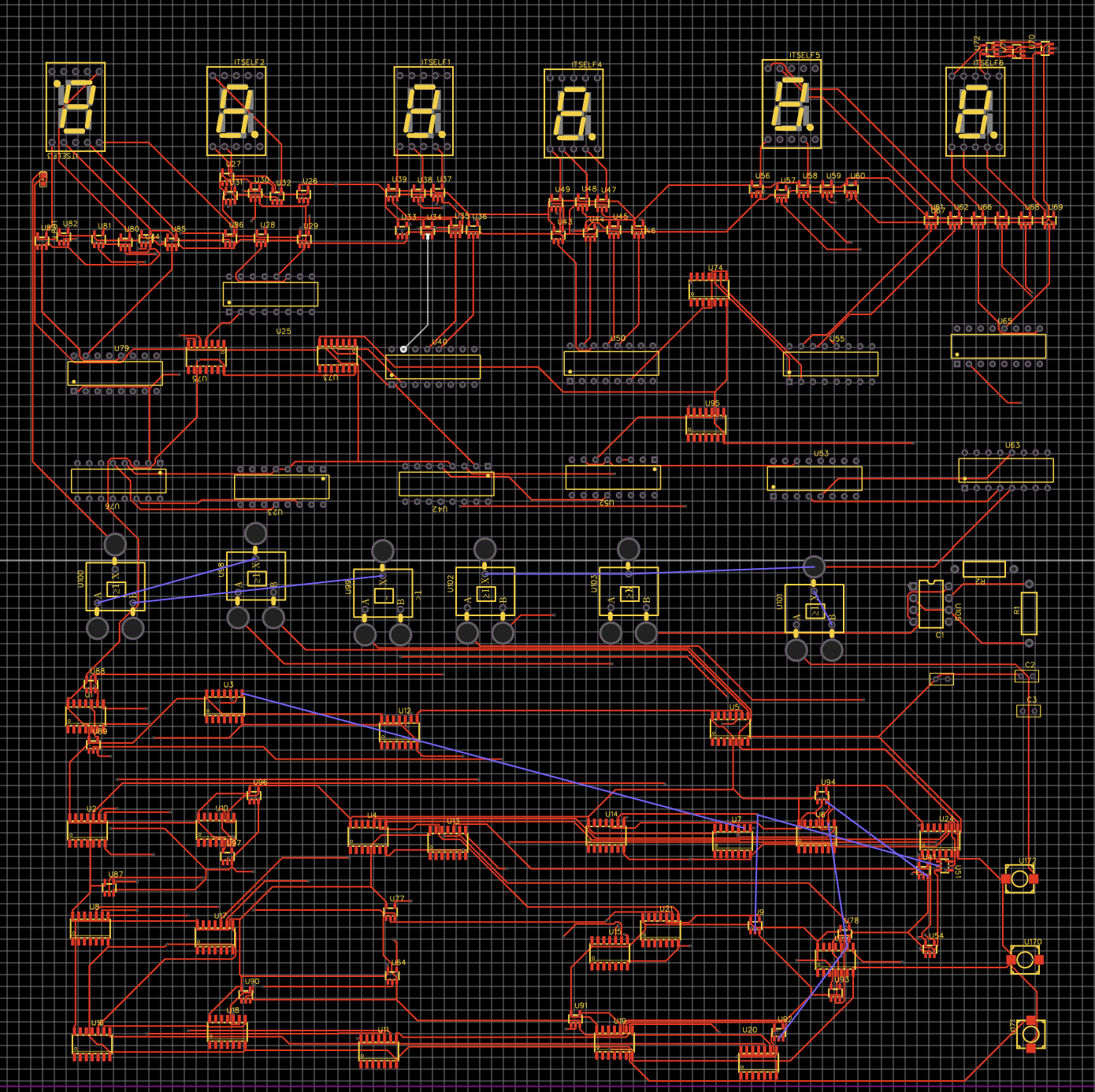
Timer PCB auto routing on Easy EDA
Design of a 7-segment display on Easy EDA
The process of designing a seven-segment display using an array of LEDs in EasyEDA involves several steps. Firstly, select the LED components and corresponding resistors to control current flow. Arrange the LEDs in patterns representing the numbers 0-9, connecting the anodes of LEDs within each segment. Establish connections from these segments to a control source, like a microcontroller, by linking the anodes to output pins and the cathodes with resistors. Ensure proper grounding for the cathodes and connect power through resistors to the anodes. Simulate the circuit in EasyEDA to detect and rectify any errors. Test the display functionality by applying voltage and signaling different numbers. Iterate on the design, adjusting resistor values or connections if necessary for optimal performance and brightness. Clear labeling and color-coding aid in organization and troubleshooting throughout the process.
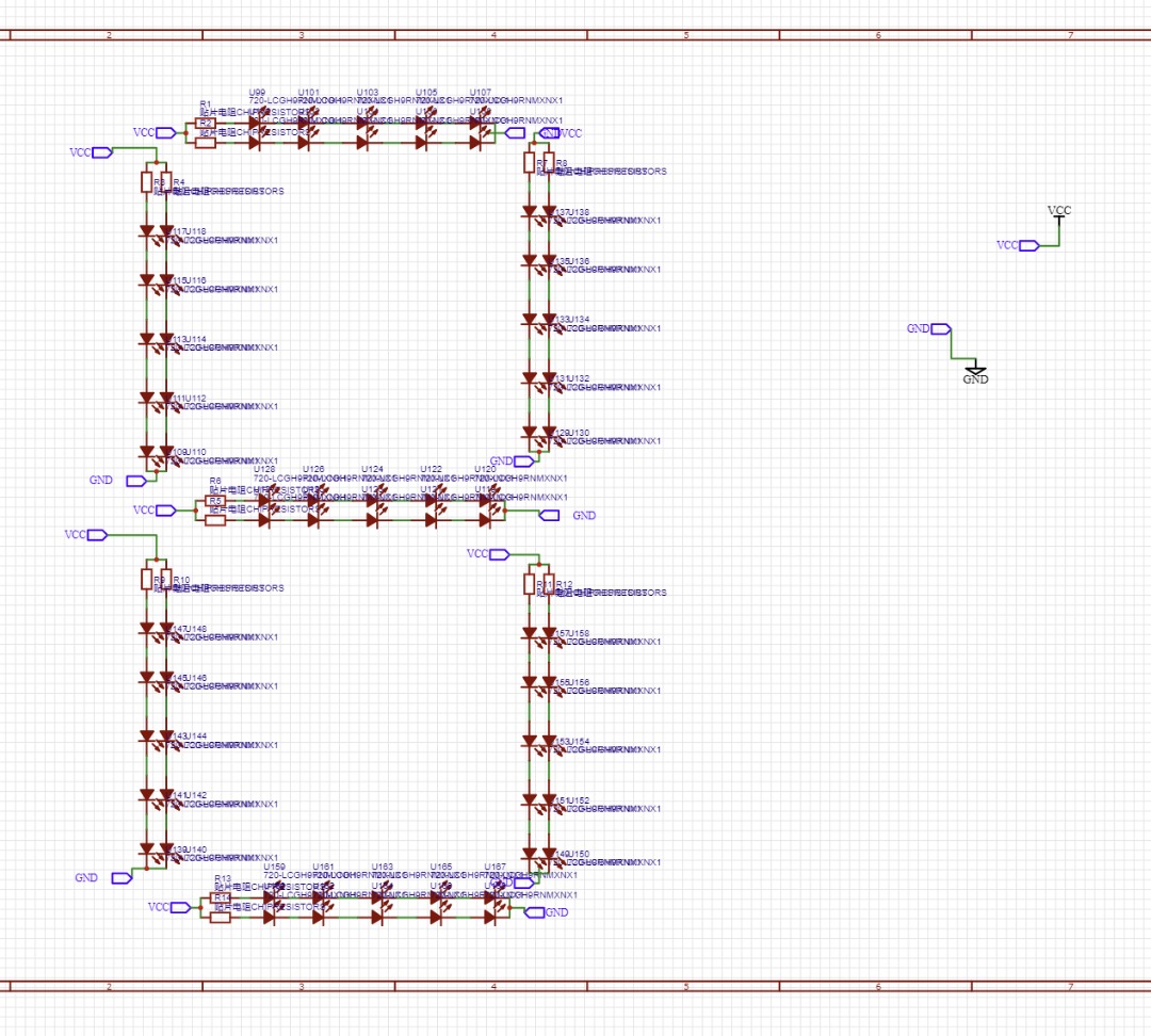
Fig 2b: 7-segment display schematic on Easy EDA

Fig 2c: 7-segment PCB
Design of a 5-V power supply
The creation of a 5V power supply in EasyEDA involved several steps. Using the software, the LM7805 voltage regulator component was selected from the libraries and placed onto the schematic editor. Connections were established from the input pin of the regulator to a power source symbol representing a higher input voltage, while the ground pin was linked to the system ground symbol. Capacitors were added near the input and output pins of the regulator to enhance stability, with their legs connected to the corresponding pins and the system ground. Careful labeling and annotation ensured clarity in the schematic, and the connections were thoroughly reviewed for accuracy. Upon completion of the schematic, the circuit was simulated using EasyEDA's tools to ensure a stable 5V output despite variations in the input voltage or load conditions. Any necessary adjustments to capacitor values or additional components for improved stability were made based on simulation results. The schematic was then converted to the PCB layout editor, where components were positioned, tracks were routed, and the design was finalized.
Fig 2d: Power-supply schematic on Easy EDA