Design and Simulation of a 12-Hour Digital Clock
Demo of Circuit
Description of Lab
The goal of this project is to design a digital clock with additional functionalities. As a result, a 12-hour clock was designed to operate from mains, tick accurately every second, beep every 15 minutes, and have a means to set time. The designed clock was first simulated in Logisim. Then, a schematic was designed in EasyEDA and the PCB was generated. The components used were:
- 6 × 7-segment displays
- 6 × BCD to 7-segment display decoders
- 7 × modulo 15 counters
- 3 × buttons or switches
- AND logic gates
- OR logic gates
- NOT logic gates
- Resistors
- Capacitors
- An LED
- A buzzer
- A transformer
- A voltage regulator
- Vcc voltage source
- Ground
- A transformer
- An NE555 timer
- A D flip-flop
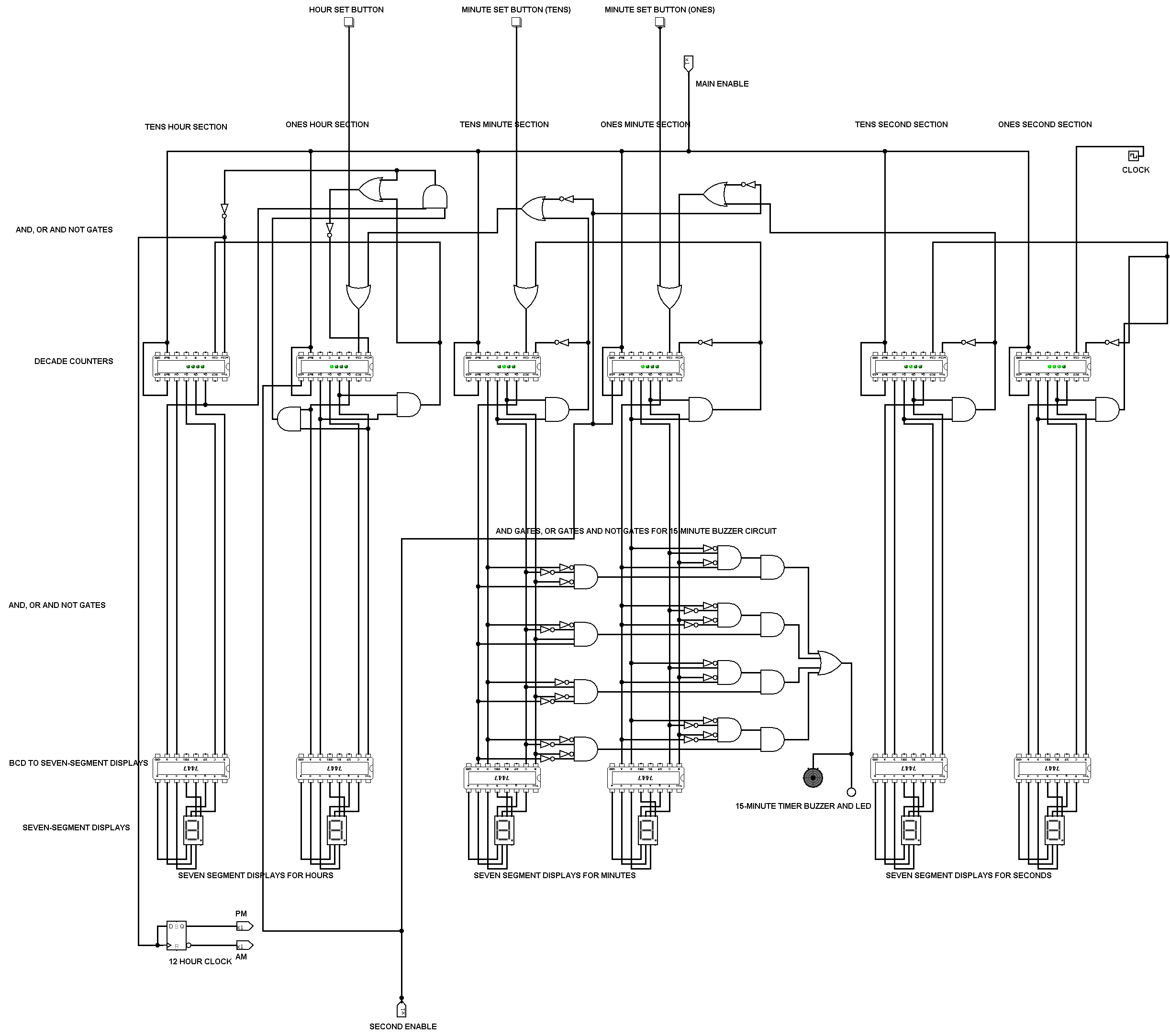
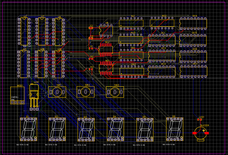
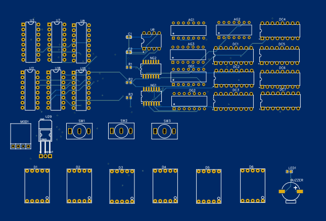
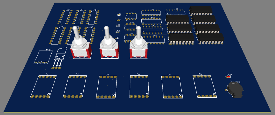
The designed digital clock receives its clock input from the NE555 timer circuit designed with a 20k and a 50k resistor, and a 10uF capacitor to produce a frequency of 2Hz to tick every second. The clock of the circuit sends its signal through the modulo 15 counters, through the BCD to 7-segment display decoders to the 7-segment displays, through several combinations of AND, OR, and NOT logic gates. Additionally, a 15-minute buzzer circuit was designed specifically with a combination of AND, OR, and NOT gates for the accurate buzzing of the clock at 15-minute intervals. An LED was connected with the buzzer for a visual representation of the 15-minute indicated intervals. Finally, the clock was designed as a 12-hour clock using a D flip-flop with switches to enable the setting of time. Below are variation of images of the designed digital clock.
Logisim Design

EasyEDA Schematic Design

PCB Design


3D Model of PCB

The various images show the various steps that were taken to design the PCB of the clock, as well as their different representations.